Hello, welcome to browse the website of Dongguan Ruibang Model Manufacturing Technology Co., Ltd.!
National service hotline
+86 136 2267 3276

Views: 59 Author: Site Editor Publish Time: 2024-11-15 Origin: Site


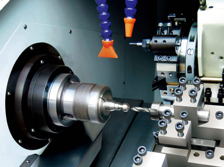
In projects that use CNC machining , wall thickness is an important factor in achieving optimal results. This article will explore in-depth the significance of wall thickness in CNC machining and how it directly affects the quality and performance of parts.
Wall thickness is a key parameter in CNC machining, referring to the specific dimensions of the material layer between two parallel surfaces of the part. Simply put, it maintains the structure of the parts so that it maintains lightweight and efficient while having the necessary strength. In CNC processing, the wall thickness must be calculated based on material characteristics and part functions. For example, lightweight applications may require thin walls, but thin wall processing needs to be precise to prevent warping or breakage; thick walls increase durability, but increase weight and cost and reduce production efficiency.
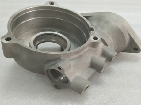
Wall thickness directly affects the structural integrity of the parts. Overthin walls are prone to deform when they are loaded, resulting in operational failures, which is particularly critical in high-stress industries such as automobiles and aerospace. Although excessively thick walls provide more strength, they will increase unnecessary material use, weight and cost. No additional functional benefits.
Mechanical stability refers to the ability of a part to maintain shape and size during and after processing. Appropriate wall thickness ensures that parts are stable during processing, reduces tool skew or vibration, and ensures tight tolerances and ideal surface finish in precision applications.
When selecting CNC processing materials, the wall thickness must be considered to ensure that the material characteristics meet the design functional requirements. For example, metals such as aluminum and brass can be processed with thinner walls due to their strength and rigidity; plastics may need thicker walls to maintain structural integrity under load or high temperature environments.
1. Structural strength : Thick walls provide higher structural strength and are crucial for parts that withstand large mechanical loads.
2. Thermal stability : The wall thickness affects the material's ability to resist changes in temperature caused by changes in shape, which is particularly evident in high-performance applications.
3. Weight : The wall thickness directly determines the final part weight. In industries such as aerospace and automobiles, minimizing weight is a key factor.
4. Cost : Thick walls usually mean more materials are used, resulting in increased costs, so optimizing wall thickness is crucial to balance performance and cost-effectiveness.
Different materials have different minimum and maximum wall thickness ranges while maintaining structural integrity and processability. For example, the minimum wall thickness of aluminum is 0.5mm, the maximum wall thickness is 10mm; the minimum wall thickness of stainless steel is 1mm, the maximum wall thickness is 15mm, etc.

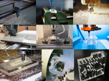
Wall thickness significantly affects processability. During thin-wall processing, the tool skew and vibration risks are high, affecting the accuracy and surface finish. The processing process needs to be accurately controlled and the speed and feed capacity are adjusted. Thick wall processing is more stable, reducing the possibility of deformation or warping, and more aggressive processing parameters can be used to improve efficiency, but more material removal is also required, increasing processing time and cost.
Part wall thickness affects tool selection. Thin-walled parts require specially designed tools to reduce skew and remain sharp for a long time. They are usually coated or geometrically to ensure high-precision processing. Thick-walled parts require tools that can efficiently remove a large amount of materials without affecting accuracy, and pay more attention to rigidity and durability.
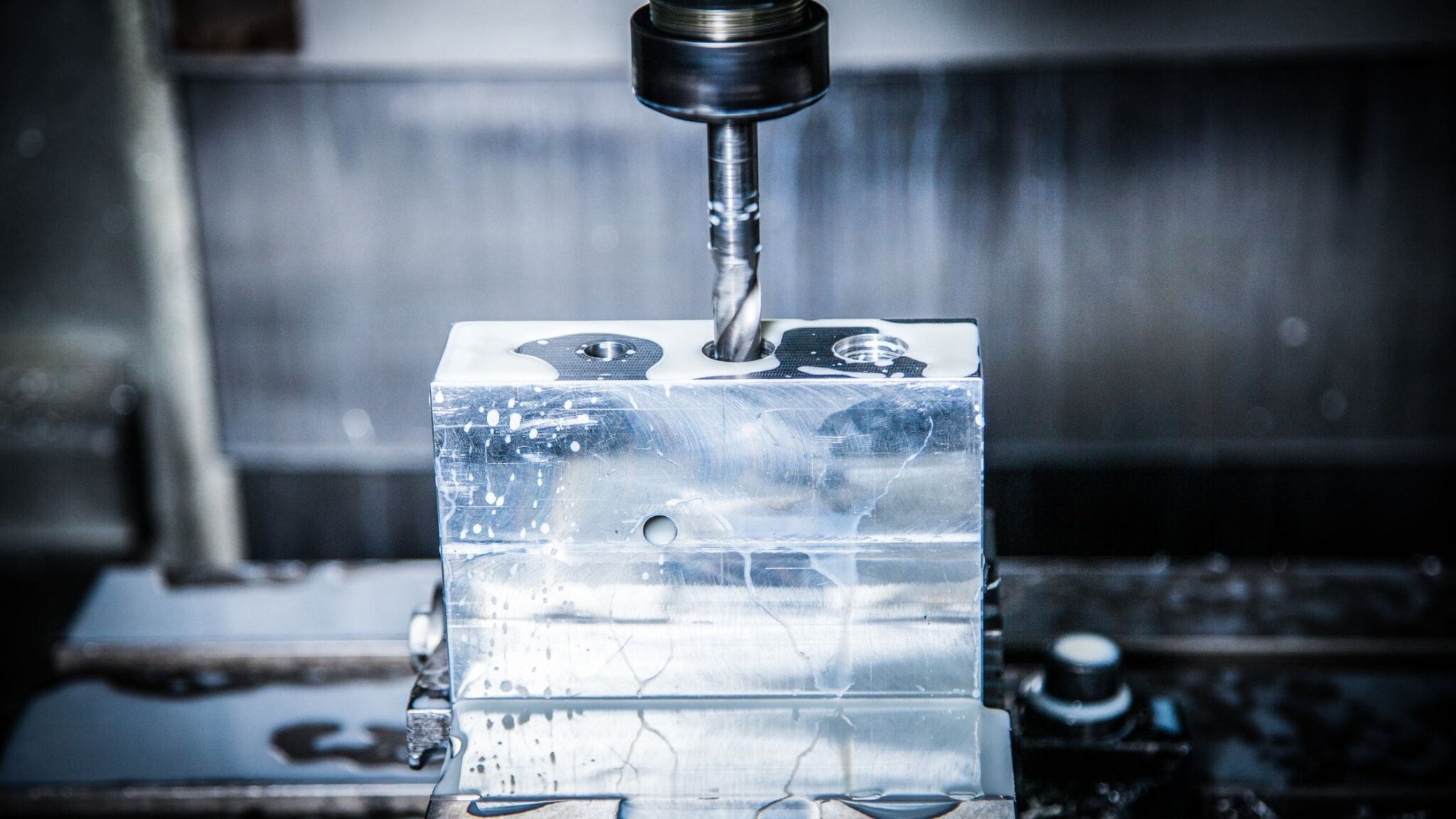
Wall thickness affects processing parameters such as cutting speed, feed rate and cutting depth. Thin-wall processing requires reducing the cutting depth and feed rate to prevent vibration and tool skew and maintaining structural integrity; thick-wall processing can be more aggressive, but attention should be paid to thermal management to avoid thermal deformation, especially for materials such as stainless steel or brass. , requires proper cooling and lubrication.
There are unique challenges in machining parts with different wall thicknesses. For example, parts with thin and thick wall parts may require multiple tool changes or adjustments to increase complexity. Careful planning is required to ensure that each part is processed in accordance with specifications and does not affect the overall quality. .
Calipers are multi-functional measuring tools, often used to measure the distance between two opposite parts in CNC machining, because of their ease of use and accuracy, they are often used to check wall thickness. Calipers are available in digital, dial and vernier styles, with varying accuracy and convenience. Its advantages include versatility, ease of use and high accuracy of digital calipers; disadvantages are limited measurement range, manual operation may introduce human error, and high requirements for measuring surfaces.
Micrometers are precision measurement tools for precise measurement of small sizes. They are often used to measure wall thickness in CNC machining, especially in cases where accuracy is required. There are many types, such as outer diameter micrometer, inner diameter micrometer and depth micrometer. Its advantages are high accuracy, consistent measurement and versatile; its disadvantages are limited measurement range, training and experience are required to use accurately, and manual operation may lead to measurement differences.
Ultrasonic thickness gauge uses sound waves to measure material thickness without loss. It is suitable for measuring wall thickness of parts that are difficult to reach or cannot be damaged. It is widely used in the metal, plastic and composite materials industries. Its advantages are non-destructive, suitable for a variety of materials, easy to use and fast reading; its disadvantages are that it needs to be calibrated for specific materials, affects accuracy and is cost-effective.
X-ray and CT imaging are used in cases where traditional contact measurement tools are not feasible, creating detailed cross-sectional views of the parts that accurately measure the inner and outer walls. X-rays provide 2D views, and CT imaging provides 3D reconstruction. Its advantages are non-destructive, detailed visualization, and multi-functional; its disadvantages are that the equipment is expensive, requires professional facilities and personnel to operate, and is time-consuming.
Optical and laser micrometers are contactless measurement tools that measure surface distances using light or laser beams. They are suitable for precise measurements and without physical contact, such as precision or high polished surfaces. Its advantages are high accuracy, fast speed, and non-contact measurements to prevent surface damage; its disadvantages are that the surface finish affects the accuracy, has a limited measurement range, and is high cost.
Eddy current thickness gauge is a contactless device that uses electromagnetic induction to measure the thickness of nonferrous metals and is useful in industries where precision and non-destructive testing are crucial. Its advantages are non-destructive testing, high accuracy and versatile functions; its disadvantages are mainly used for non-ferrous metals, surface conditions affect accuracy and require regular calibration.
A feeler gauge is a simple mechanical tool consisting of a set of thin metal sheets of varying thicknesses for measuring gaps or wall thickness. Its advantages are simple and easy to use, no professional training, durability and no calibration required; its disadvantages are that manual operation depends on user skills and judgment, limited accuracy, and is not suitable for soft or fragile materials.
The minimum wall thickness that can be achieved depends on the material, CNC machine capability and specific design requirements. For example, the minimum wall thickness of aluminum can reach 0.5mm, because of its good workability and high strength, it is suitable for lightweight applications; the minimum wall thickness of stainless steel is 1mm, with high hardness, so that thin walls require more precise processing and tool control; The minimum wall thickness of brass is 0.5mm, easy to process, and is suitable for parts that require fine details and thin walls; the minimum wall thickness of plastic is 0.3mm, but due to its flexibility and low strength, thin walls are often used for applications that are not subject to large mechanical loads; Composite materials such as carbon fiber have a minimum wall thickness of 0.8mm, so you should pay attention to avoid stratification during processing.
Aluminum has processable wall thicknesses up to several inches, suitable for parts that require high structural strength and do not add too much weight; stainless steel has processable wall thicknesses up to 3 inches or more due to density and strength, suitable for durable and harsh Conditioned parts; brass is easy to process and can handle wall thickness up to 2 inches, suitable for applications requiring a combination of strength and fine details; plastic can process thick walls but are limited by the risk of material rigidity and warpage, such as ABS can reach 1 inch The wall is thick without obvious deformation.
Achieving the required wall thickness in CNC machining not only involves material and machine tool capabilities, but also requires balancing costs, tolerances and part-specific requirements. Thick walls increase material cost and processing time, and maintaining tight tolerances of thick walls is challenging, especially materials that are susceptible to heat deformation. Designers must weigh wall thickness, part performance and manufacturing efficiency, such as thick walls increase strength but make parts heavier and difficult to process, thin walls save material and machining time but may affect strength and durability.
Choose high-strength weight ratio materials such as aluminum and titanium to maintain structural integrity even if the wall thickness is reduced. At the same time, taking into account material machiningability, difficult-to-process materials may require thicker walls to avoid deformation during manufacturing.
The minimum wall thickness is determined based on the expected use of the part, non-load-bearing parts can be thin as 0.5mm, and load-bearing parts need to be thicker walls to increase strength, and balance weight loss and structural integrity are tested through simulation and prototype.
Add ribs or gussets to reinforce thin walls to avoid stress concentration and reduce the risk of deformation during use. At the same time, rounded corners or chamfers are used instead of sharp corners.
Use short cutting tools to reduce skew, adjust machining parameters such as feed rate and cutting speed, reduce the stress on the tool and parts, and ensure uniform wall thickness and surface finish.
Considering the thermal expansion characteristics of the material, especially when processing heat-prone plastics or metals, cooling strategies such as using coolant or air injection to maintain dimensional accuracy and prevent thermal damage.
Perform FEA simulation to predict the behavior of parts under load, identify potential weaknesses in the design, adjust wall thickness and reinforcement characteristics before processing, and simulate different machining scenarios to determine the optimal wall thickness for balanced performance, weight and manufacturability.
Consider the surface treatment process after processing, such as anodizing or electroplating, to ensure that the wall thickness after treatment meets the specifications, and choose the surface treatment method that has the least impact on the stress in the thin-wall area.
Work closely with CNC mechanics on the design stage to obtain insights on tool selection, machining strategies and potential challenges, conduct prototype testing together, and perfect the design before mass production.
The formula for calculating wall thickness usually depends on the design requirements and the specific application. For cylindrical parts (such as pipes or pipes), the commonly used formula is: wall thickness = (outer diameter - inner diameter) / 2. For other types of parts, wall thickness may need to be calculated based on specific design considerations such as maximum stress or minimum material thickness required for structural integrity. For example, a cylindrical sleeve with an outer diameter of 100mm and an inner diameter of 90mm has a wall thickness = (100mm - 90mm)/2 = 5mm, which ensures that the sleeve has sufficient material to maintain its shape and to withstand mechanical loads in use.
Wall thickness is often restricted by common standards in the CNC processing industry, especially in industries with high requirements for accuracy and durability. For example, ASME B31.3 specifies the minimum wall thickness of process industrial pipes to ensure that the pipes are subject to internal pressure and external loads; ISO 2768 specifies linear and angular dimensional tolerances, which indirectly affects the wall thickness and ensures that the wall is not thin or too thick; DIN 16901 manages plastic injection molding Part design, focusing on wall thickness uniformity; MIL - STD - 31000 requires detailed records of design aspects including wall thickness; ASTM D4976 stipulates polyethylene material requirements, including appropriate wall thickness for different applications.

Each material has specific properties, and improper selection of wall thickness can lead to problems such as thin walls of plastic or soft metal that are prone to warping or breaking.
Tool skew will cause changes in wall thickness. When processing thin walls, you need to select the appropriate tool and adjust the parameters.
The heat generated during processing causes the material to expand. Without considering the thermal expansion, it will lead to incorrect parts sizes, affecting assembly and function. Special attention should be paid when processing materials that are prone to thermal expansion (such as aluminum).
Thin walls are prone to vibrating and moving during processing, resulting in inaccurate cutting, and sufficient support structures or fixtures are required to fix the parts.
Each material and processing process has a minimum wall thickness that can be achieved, and neglected can lead to fragility or prone to defects in the parts. Following the CNC machining minimum wall thickness principle can avoid these problems.
Wall thickness affects every stage of CNC processing , from material selection to surface finish. This article covers key considerations from material selection to processing parameter optimization. Wall thickness must not be ignored. Careful planning and execution are the key to achieving the best results. For further study, please refer to detailed CNC machining design guidelines or consult industry experts.
When using a 0.4mm nozzle, the minimum wall thickness is about 0.8mm, ensuring structural integrity and maintaining 3D printing or CNC machining accuracy.
When using a 0.8mm nozzle, the wall thickness can be as thin as 1.6mm, which balances strength and material efficiency, and is suitable for parts with larger and durable walls.
Dongguan Ruibang Model Manufacturing Technology Co., Ltd. focuses on CNC precision machining and provides manual board model manufacturing and non-standard parts processing services. The company is located in Chang'an, the hometown of Dongguan molds. The workshop area is 1,500 square meters and has 17 CNC high-speed machining centers and supporting equipment. Senior technical teams can solve processing problems and use the best solutions to control quality and cost. The products cover many fields such as machinery, automobiles, optoelectronics, home appliances, and medical care. They cooperate with many design studios and trading companies to be recognized by customers with high-quality products and reasonable prices. In terms of CNC processing wall thickness, relying on its professional strength, we provide customers in various industries with high-precision and high-quality solutions to meet different wall thickness needs and ensure excellent product performance. If you have any related processing needs, please contact Ruibang and we will serve you wholeheartedly.